Source: LDRA
Software has become the foundation for enabling rapid adoption and development of innovative technology in embedded systems, and avionics is no exception. Avionic subsystems are increasingly “software-defined,” allowing for greater flexibility with increased functionality and customization. However, as the software in these systems becomes more complex, especially those running on multicore processors, there are more opportunities for potential vulnerabilities to arise that can affect safety, security, and reliability.
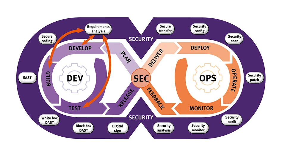
Further complicating design is the rising pace of development demanded by the marketplace. Systems need to be updated more frequency, not only to remain competitive with new features and capabilities, but also to meet the increasing challenge of maintaining security in complex connected systems. Development approaches like DevSecOps that employ development methodologies like Continuous Integration/Continuous Deployment (CI/CD) are essential for developers to be able to deliver functionality faster than ever before (see Figure 1 above).
Functional safety and security
The avionics system must comply with a wide range of standards to ensure they meet strict government and idustry regulations for functional safety, security, and reliability. These standards outline varying levels of compliance, depending upon the criticality of the software in the system. The more critical the code, the more comprehensive the testing and validation that will be required.
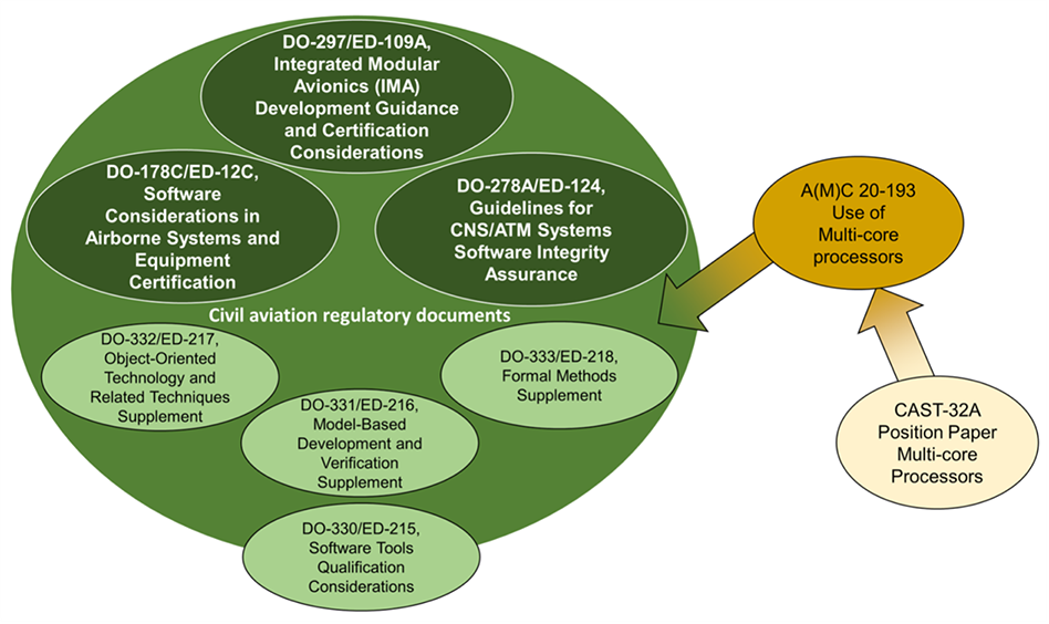
Consider CAST-32A, AMC 20-193, and AC 20-193 (see Figure 2). CAST-32A outlines important considerationsfor designing with multicore processors, including non-prescriptive Software Development Life Cycle (SDLC) objectives that can guide and support developers toward adhering to industry standards like DO-178C. Note that in Europe, AMC 20-193 has superseded CAST-32A, and AC 20-193 is expected to do the same in the U.S.
Worst-Case Execution Time
One of the most important – and difficult to assess – characteristics of a multicore-based system is its Worst-Case Execution Time (WCET). Because tasks running on different cores on the same processor share resources, there is the possibility of contention for these resources. Resource contention can occur at the application level. Consider a task on Core A that needs to modify a shared system parameter. At the same time, a task on Core B needs this system parameter to make a decision. To ensure validity of the system parameter and integrity of the resulting decision, Core B must wait to access the system parameter until Core A has completed its modification and released the shared resource to be used by other cores.
However, this is not the only source of resource contention – there is also contention at the hardware level. The processor cores on a embedded target are typically wired to a shared cache and shared memory. Often, these shared resources add additional delays and contentions – from the hardware – that are entirely invisible at the application level.
Such contention delays add variability to execution time. As delays may or may not be experienced during a particular run-time instance, this causes the expected execution time of code to vary across a widespread. For example, Figure 3 shows the range of possible execution times for a task.
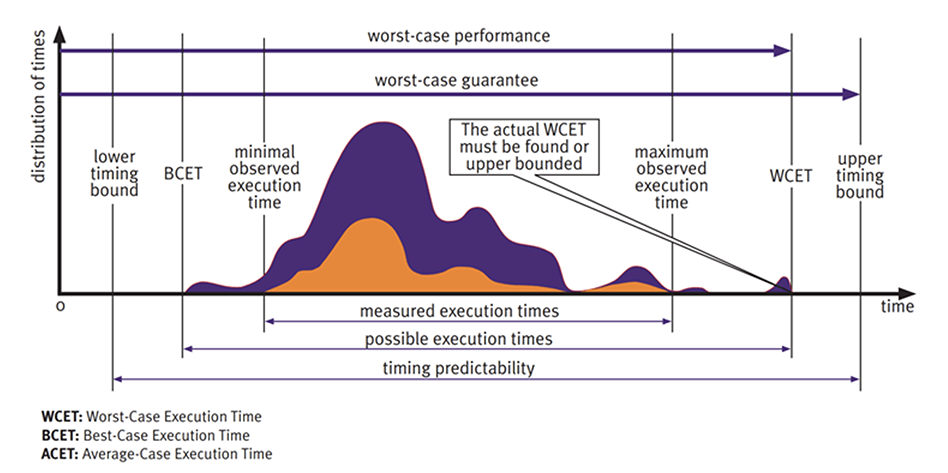
It is important to note that the best- and worst-case execution time (WCET) for a task is based on a sample of observed execution times. Given the unpredictable variability of contention between cores from run to run, it is extremely difficult to calculate the maximum possible (actual) WCET. This is because what matters here is the contention that arises between cores is dependent upon the tasks other cores are actually executing at run-time. This means that it is often not feasible to verify the impact of every possible contention between cores. In fact, the circumstances that trigger the actual WCET may happen so infrequently that they are never observed in the lab. This does not, however, mean they won’t ever occur out in the field. Rather, they are a potential failure waiting to happen with the possible outcome of injury or death.
This is what functional safety standards aim to prevent. The goal of WCET analysis is to use observed execution times to estimate the WCET. To guarantee that all real-time timing requirements are met, developers add a buffer to provide an upper timing bound that ensures the actual WCET falls within an acceptable range.
Analyzing Worst-Case Execution Time
Multiple approaches have been shown to effectively analyze WCET to meet CAST-32A and A(M)C 20-193 guidelines in systems based on multicore processors. Three commonly used methods include:
Static analysis of the code: The traditional approach to look at processor variability was to look at the code statically and at the instruction level. Metrics such as Halstead metrics allow you to bound the complexity and measure how many instructions a particular routine may compile into. However, with the advent of highly pipelined processors with variable instruction execute speeds, these metrics are no longer enough – in and of themselves – to predict the time to execute a routine and cannot predict the variability.
Empirical analysis of execution times: This approach measures, analyzes, and tracks individual execution times through dynamic analysis. To ensure accuracy, analysis must occur in the actual environment in which the application will operate or an equivalent (such as a digital twin). This eliminates the impact of factors such as complier / linker options and differences in the implementation of hardware features. Analysis must also include sufficient repeated tests to capture environmental and application variations between runs. Automated tools simplify dynamic analysis by streamlining the testing process, reducing the possibility of human error, and ensuring accurate and consistent results.
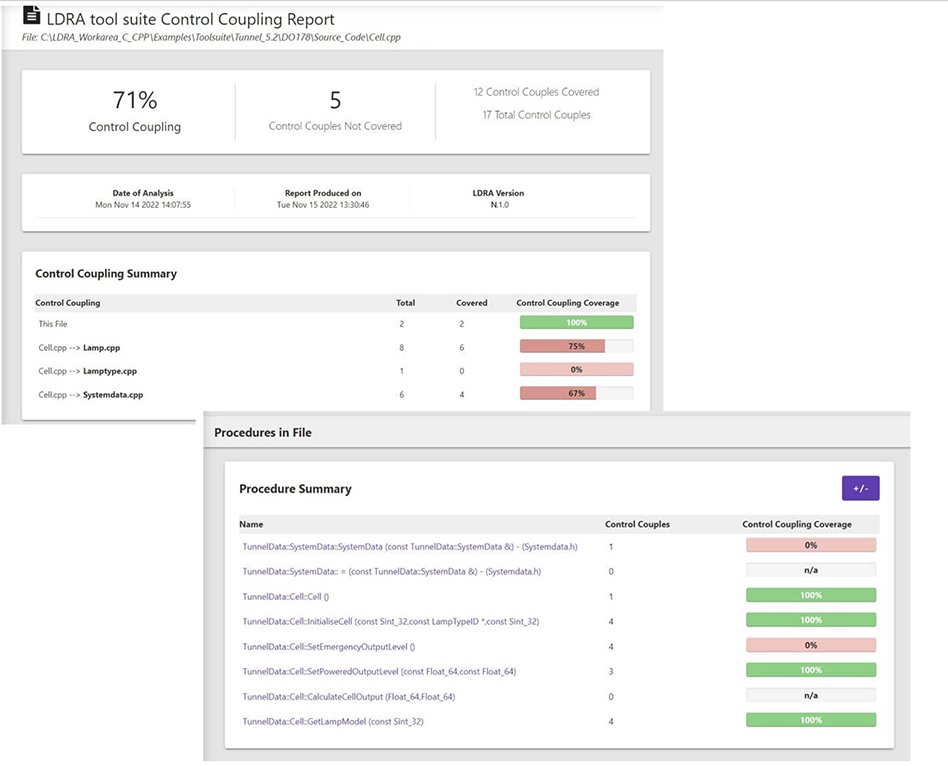
Control and data coupling analysis: Data coupling analysis identifies data dependencies while control coupling analysis identifies task dependencies within an application. Many standards require that all couples be exercised to reveal potential issues that could arise between the interaction of control and data dependencies (see Figure 3). Data and Control Coupling can be explicit or implicit – when multiple processors are using the same data buses, to cache and memory, this adds implicit data and control coupling. By examining the dispatch table and understanding what parts of the application execute together and separately, data and control coupling analysis allows us to isolate parts that may otherwise interfere with each other.
Continuous verification
Verification of compliance with standards or guidelines such as CAST-32A is an essential element of the design cycle for avionics applications. As can be seen from the three types of analysis listed above, WCET analysis can begin during early design stages and continue through to deployment, maintenance, and updates. For example, static analysis can provide early guidance that enables developers to significantly reduce the number of real-time timing issues they have to deal with in later design stages. Empirical analysis takes place during later stages after there is a target available to run software on.
This design approach is known as Shifting Left (see Figure 4). Rather than wait to perform all testing until after software has been designed, early stage testing identifies issues sooner when they tend to be easier and less expensive to resolve. Importantly, we can discover timing faults and data and control coupling caches, as we develop our application, rather than wait until the end of development and find that our application does not run reliably.
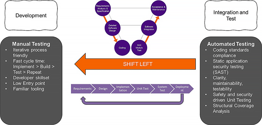
Figure 5: Shifting Left is a design methodology focused on uncovering potential issues sooner in the development lifecycle to mitigate risk and often results in a less costly resolution. (Source: LDRA)
In fact, key to creating safe, secure, and reliable software is a robust development process that integrates verification through every stage of design, a process known as Continuous Verification. For example, Halstead Complexity Metrics can be used throughout the entire design lifecycle of software. The same tools that can help developers restructure early code to reduce the risk of creating multicore-based timing issues can be used to identify bloated code that has slowly become too complex over time.
Continuous Verification works in conjunction with Continuous Integration/Continuous Deployment to accelerate the verification process in parallel to the development and delivery processes. By integrating Continuous Verification within the design tool chain and development environment, verification becomes a transparent part of the design flow. And when verification is automated – including running tests and metrics, consolidating results across the development team, and creating the necessary reports – compliance is substantially simplified while providing greater accuracy and consistency.
The software in today’s avionics systems is only going to grow more complex tomorrow. By integrating testing and verification into every design stage, developers can benefit from Continuous Verification, leading to faster development of software, accelerated time to delivery, and simplified compliance, all while assuring safety, security, and reliability.
https://ldra.com
About the author: Jay Thomas, technical development manager for LDRA, has worked on embedded controls simulation, processor simulation, mission- and safety-critical flight software, and communications applications in the aerospace industry. His focus on embedded verification implementation ensures that LDRA clients in aerospace, medical, and industrial sectors are well grounded in safety-, mission-, and security-critical processes. He can be reached at jay.thomas@ldra-usa.com
Latest from Aerospace Manufacturing and Design
- Assemble-to-order program for gundrilling machines
- #83 Manufacturing Matters - Workholding Roundtable
- Increase speed, productivity, and agility with automation technology
- Real-world manufacturing insights from industry experts
- The Lee Company opens Innovation Center
- Precision XY gantry system
- Archer to test Starlink onboard its Midnight air taxis
- System eliminates cage-creep in sliding bearings