The vast majority of external heatsinks are designed to work in a single orientation with respect to gravity. Geometry dictates that the conventional finned heatsink will be far more efficient when air is moving parallel to the orientation of its fins. But Crane Aerospace & Electronics Mechanical Engineer Mark Resler faced the challenge of designing a fin that would work either vertically or horizontally. Developing an entirely new heatsink geometry that would have met the performance requirements would have taken an enormous amount of time using conventional build and test methods. Instead, Resler simulated a range of different heatsink configurations using thermal simulation software. He determined that an unusual design with a plate and standoffs provided the best performance. Then he performed a parametric study to optimize the design from a dimensional standpoint.
Proposal Presents Design Challenge
Crane Aerospace & Electronics supplies critical systems and components to the aerospace and defense markets. Recently, a customer asked the company for a proposal for a DC power subsystem for a commercial airliner. Two of these subsystems will fly in each airliner, one in the horizontal and the other in the vertical orientation. This provided a major design challenge because external heatsinks work efficiently only in one orientation. The fins are normally aligned with the gravitational forces so that rising air will pass between the fins so that the fins can effectively conduct heat to the air. If the fins were perpendicular to the gravitational forces, then the rising air would contact only the lowest fin and the rest of the heatsink would not be engaged.
The enclosure for the subsystem is about 8" wide x 11" long x 3" deep. The electronics in the box dissipates approximately 110W. A fan is used to provide air cooling; however, the design specifications dictate that the box will continue to operate even in the case of fan failure, so this condition dictates the design of the cooling system. Most of the heat is generated by several power semiconductors located along the 11" x 3" edges of the box. The terminal blocks are mounted on the inside of the top 6" x 3" surface, and the fans are mounted inside the 6" x 3" bottom surface.
Normally, this type of system would use fin-type heatsinks on the exterior sidewalls of the enclosure. But in this case, the default design would only work in the horizontal or vertical orientation, but not in both. Resler considered a number of possible design configurations. An early idea that appeared promising was to use fins at a 45° angle to the walls of the enclosure so that air would flow across the fins, whether the box was mounted vertically or horizontally. Of course, it would be possible to make this or nearly any other heatsink design work as long as space and weight were not a major concern. But as in nearly every aerospace application, space and weight were both major concerns, so Resler needed to keep the heatsink as small and as light as possible.
Identifying Possible Solutions
Resler brainstormed with other Crane engineers and developed six alternative heatsink configurations. Five of these designs used conventional "U" or "hat" shaped sheet metal fins that are typically spot-welded to the chassis side walls. One design used a flat sheet metal plate with standoffs to secure it to the wall of the chassis. This type of fin is lighter and less expensive to manufacture than conventional fins. The fin is supported by aluminum standoffs that are approximately 0.300" long. The standoffs are connected to the power semiconductors and conduct heat directly to the fins. Here is a description of each configuration:
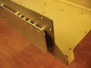
- Plate and standoffs. This heatsink design consists of an aluminum plate parallel with the side wall and supported by 18 aluminum standoffs. (See Figures 1 and 2 on page 74.) The standoffs were positioned directly adjacent to the heat sources so in addition to supporting the outside plate, they also promote heat conduction.
- Short fins. This heatsink design consists of U-shaped fin sections that are parallel with the short side of the well. (See Figures 3 and 4 on page 75.) The base of each U-shaped section is welded to the side wall and two fins protrude perpendicular to the side wall. This design had 16 U-shaped sections for a total of 32 equal-length short fins.
- Long fins. This design consists of Ushaped fin sections that are parallel with the long side of the side wall. The base of each U-shaped section is welded to the side wall and two fins protrude perpendicular to the side wall. This design had four U-shaped sections for a total of eight equal-length long fins.
- 45° angle fins. This design uses Ushaped fin sections oriented 45° from the sidewall edges. The base of each U-shaped fin is welded to the sidewall. This model has 11 U-shaped sections.
- Short flanged fins with outer flange. This design uses U-shaped fin sections parallel to the side wall – the same as the short fins configuration – except on each U-shaped section an outer flange is added to one fin.
- 45° angled fins with outer flange. This design uses U-shaped fin sections at a 45° angle to the side wall – the same as configuration four – except on each U-shaped section an outer flange is added to one fin.
Thermal Simulation Evaluates Design Concepts
The conventional approach to evaluating these concepts would be to build prototypes and test their performance. But this approach is expensive and time-consuming and the customer had asked Crane to deliver their proposal in a relatively short time period. Thermal simulation made it possible for Resler to quickly evaluate a wide range of designs at a relatively low cost. Thermal simulation also provides extensive information including not only the temperatures, but also airflow and pressure distributions that help diagnose and rapidly improve the performance of a particular design.


Resler modeled these designs using Flomerics' Flotherm thermal simulation software. While Flotherm has the ability to import a solid model, in this case Resler generated the geometry from scratch. He used the pattern generator in Flotherm to produce the fins. Modeling the 45° fins with prism elements would have resulted in a very large model, so the fins were modeled as cuboids and the side wall was modeled at 45° using seven prism elements. The two gravity conditions were modeled at 45° to simulate vertical and horizontal mounting.
"Flotherm quickly generates a model and makes it easy to change boundary conditions, environmental conditions and gravitational direction," Resler says. "I used these capabilities to model all six geometries at various altitudes and ambient temperatures."
Because the unit size was constrained by the design specification, Resler kept the envelope of each design the same for each model. Resler ran the simulation results twice for each design, in the horizontal and vertical orientations. It is important to minimize both temperature rise and weight so the product of these two simulation results is calculated as a parameter to measure overall heatsink performance in both the horizontal and vertical orientation. The plate and standoff design provides the best overall performance for both horizontal and vertical mounting.
Optimized Solution


Resler then proceeded to perform a trade study that involved simulating the performance of the plate and standoff design while varying the length of the standoff. "We tried moving the heatsink closer to the sidewall, which would have saved space, but we discovered this made the design less effective because it restricted the airflow," Resler says.
"Building and testing several different prototype configurations would have had a significant cost and schedule impact," Resler states. "Thermal simulation allowed us to optimize the heatsink thermal performance and weight in a very short time period. Thermal simulation also enabled us to optimize the design to improve its performance to a level that would have been impossible to achieve with the build and test method within our schedule constraints."
Explore the September October 2008 Issue
Check out more from this issue and find your next story to read.
Latest from Aerospace Manufacturing and Design
- Accelerate your shop floor with smart automation strategies
- QT9 Software plans global HQ in historic downtown Batavia
- Okuma America President, CEO, & COO Jim King appointed to AMT’s Board of Directors
- Powdered metal taps – an alternative to solid carbide
- AerCap orders 100 additional Airbus A320neo family aircraft
- Renishaw to showcase high-productivity metal AM solutions at RAPID + TCT 2026
- Scrubber manufacturer adds bag filter to product line
- Hydrogen aviation OEM Beyond Aero reaches key aircraft design milestone