GIE Media

Common features on aerospace parts, holes can provide simple weight reduction, component access, mechanical assembly/movement, or critical location alignment. Feature requirements – such as diameter tolerance, finish, positional tolerance, roundness, and cylindricity – also vary. Often one of the fastest material removal operations, hole making can present challenges due to the materials, machinery, and methods used.
1) Which drill to use; indexable carbide or solid carbide?
It depends on the specifics of the hole and application. For example, holes with very long length-to-drill-diameter ratios require the strength and rigidity provided by solid carbide drills. This is also true when the hole requires a tighter International Tolerance (IT) grade. Replaceable tipped carbide drills such as Iscar’s SumoCham and Logic3cham can provide IT8 hole tolerances while delivering high material removal rates.
If you cut a variety of materials, replaceable tip drills allow users to change drill head diameter and geometry to optimize specific applications by using ISO material group-specific heads such as the SumoCham ICP, ICM, ICN, and ICK drill heads.
2) What is the benefit of having material-specific drill heads?
Changing drill geometry by quickly removing and replacing the self-clamped head tailors the drill to the material – decreasing cycle time, improving tool life, and making the process more stable. This allows more spindle uptime and throughput. For example, a SumoCham ICP head cutting Inconel 718 may suffer from chipping on the cutting edge or the chisel point due to the shearing force of the material. Changing to the ICM provides a reinforced cutting edge to withstand the pressure to shear high nickel/super alloys.
3) What are some challenges for producing holes in different materials, and do indexable products for drilling and reaming address that?
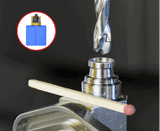
Materials with low melting points, such as aluminum, present reaming challenges as the hole tends to close on the tool, increasing friction and heat that impact tool life and finish. Diamond coatings reduce this and an indexable reaming solution, such as Iscar’s Bayo T-Ream, make it easy to apply a different head with a diamond coating. High nickel content materials, such as Inconel and titanium, also exhibit the phenomenon, so material-specific heads for drilling, such as ICN and ICM for SumoCham drills, will not have large margins that create additional friction and heat.
4) What about solutions for composites?
Layered carbon fiber reinforced plastic (CFRP) and hybrid titanium laminates can fray or delaminate from heat and cutting pressure, and composite materials are very abrasive. Iscar’s SumoCham semi-standard ICF and ICF-Ti drilling heads are diamond coated with unique cutting geometry to direct cutting forces out radially instead of axially. Iscar also offers these geometries in solid carbide with diamond coating, brazed PCD wafers, and brazed solid PCD nibs (tips).
5) Are there solutions for automated drilling units (ADU)?
Power and available force limitations on portable drilling units indicate using high-speed steel (HSS) or cobalt solid tools. Advances in cutting tool geometry and materials that reduce cutting force and horsepower required have made indexable solutions viable. Iscar offers semi-standard items, from both SUMOCHAM indexable drilling and BAYO T-REAM product lines, which feature the required special shank connectors used in popular air-driven ADUs for in-station drilling, allowing for increased performance and decreased cycle times.
For more information: https://www.iscarusa.com
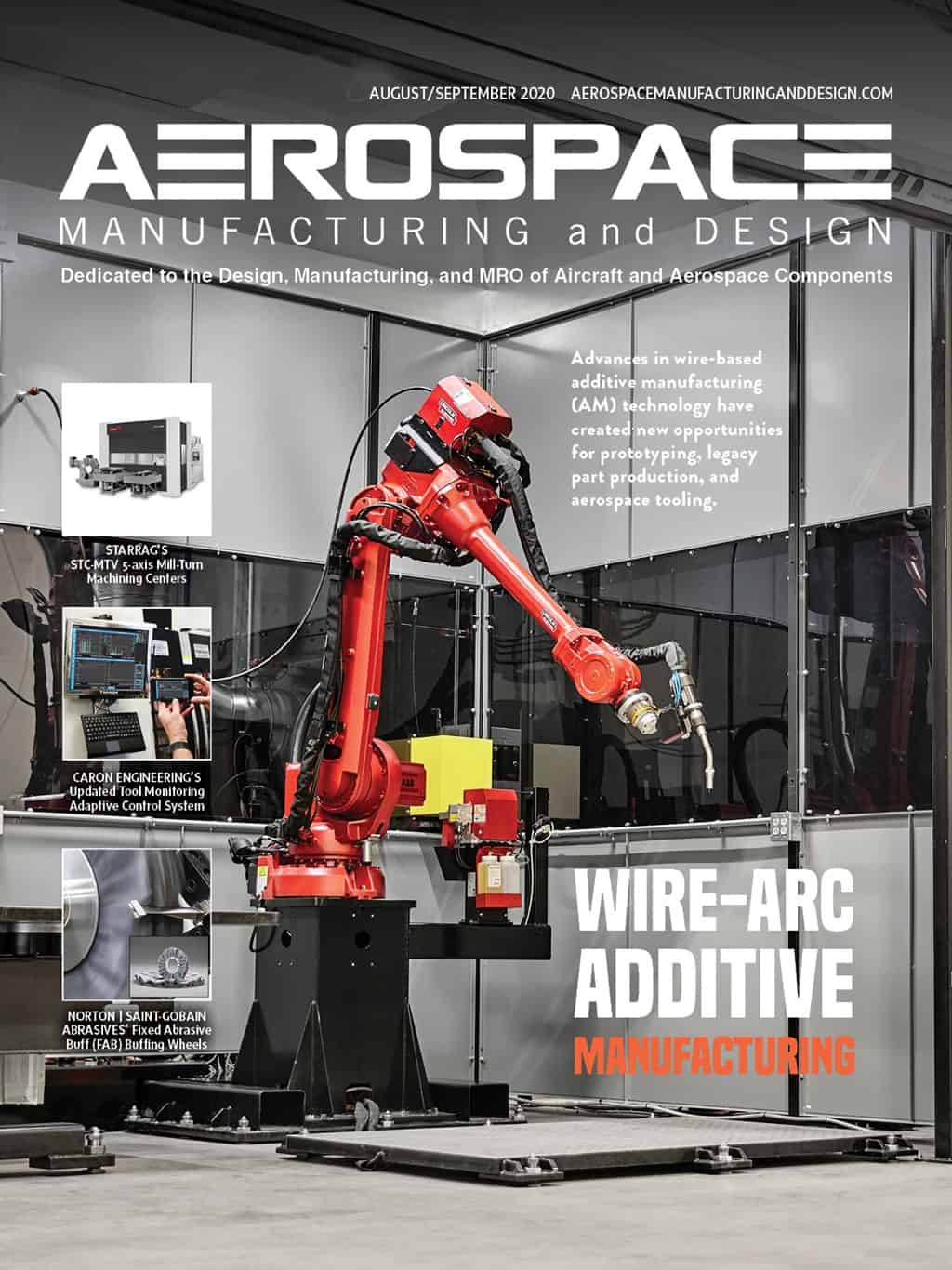
Explore the August September 2020 Issue
Check out more from this issue and find you next story to read.
Latest from Aerospace Manufacturing and Design
- US operator UrbanLink orders 20 Lilium Jets
- TJ Davies’ retention knobs
- Mazak's VC-Ez 16X for aerospace machining
- India’s IndiGo orders 30 Airbus A350 widebody aircraft
- Techman Robot unveils high-payload AI cobot TM30S at Automate
- MK Tools’ 4-fluted Rambo Speed Drill series solid carbide drills
- ASL orders 30 Reliable Robotics aircraft autonomy systems
- Fastems' Manufacturing Management Software Version 8.2