Experimental aircraft rudder-pedal gear laser-cut from 6061-T6 aluminum.
Photo credit: SendCutSend
Rapid prototyping with on-demand laser cutting is gaining traction, offering faster, more effective ways to create aerospace sheet metal parts without needing complicated manufacturing setups. Below are four laser cutting advantages for aerospace and how SendCutSend’s e-commerce model allows it to quickly process work for original equipment manufacturers (OEMs) and tier suppliers.
Laser-cut parts ready for shipment.
Precision cuts, increased accuracy
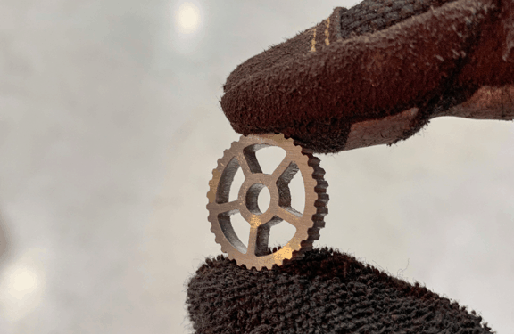
Laser cutting uses small, powerful lasers that deliver a focused beam of light with high precision to the material it’s cutting. The laser melts and evaporates material with 0.003" to 0.006" tolerances. In comparison, a plasma cutter usually has a tolerance of about 0.02", and most die-cutting tools have tolerances from 0.020" to 0.040". Laser cutters’ accuracy and precision make them a viable choice for aerospace, where tolerances are extremely tight.
Prototyping multiple designs
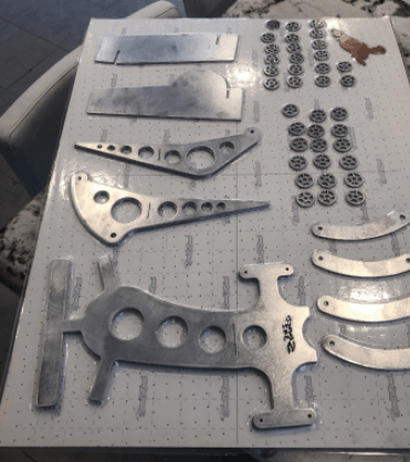
Manufacturing at scale can be expensive for aerospace manufacturers. Laser cutting allows manufacturers to test multiple design iterations in the field at low cost prior to manufacturing at scale. This method develops custom shapes and complex geometries with minimal metal distortion on completed parts. Laser-cut prototypes can be developed with a rapid turnaround for aerospace metals such as 6061-T6 aluminum, Inconel, titanium, and copper.
Cost
Laser cutting eliminates setup costs and unused parts due to design changes. You can create multiple iterations without order minimums, reducing wasted inventory. To create a component or part with a laser cutter, all that’s needed is material to cut, a laser cutter, and a schematic computer file. This significantly reduces overall costs, particularly when compared to traditional tooling and manufacturing. Laser cutters have fewer mechanical moving parts than comparable manufacturing processes, reducing maintenance and operations costs, which lowers the cost of using a laser cutting company.
Speed
A laser cutter is economical for small run projects since laser cutters don’t require custom-built or modified tooling for the application. Also, a laser doesn’t have physical cutting surfaces that wear out. Engineers can have functional parts in a couple of days, not weeks or months.
A range of laser-cut titanium parts.Rapid-prototype fixture parts for an aircraft wing assembly.
e-commerce solution
SendCutSend’s e-commerce platform allows aerospace manufacturers to get parts quickly and efficiently. Customers upload a vector file and select the metal and quantity, then the SendCutSend team reviews the file and contacts the customer with any questions. Once the project is confirmed, the file is sent to the laser for cutting and parts are shipped to the customer within three days.
One recent customer contracted SendCutSend to create assembly fixtures for a manufacturing process. Another developed prototype control panels for evaluation in simulators and ergonomic testing. Since working with SendCutSend, prototypes are developed almost as fast as they receive feedback from the testing team.
Facilities involved in maintenance, repair, and operations (MRO) face unique challenges in maintaining safe, high-performing, and durable flooring. Proper MRO facility flooring solutions maintain a safe environment while preventing damage to equipment.
Common issues
MRO facilities are frequently exposed to the elements, heavy traffic, dropping tools, and other wear sources that can damage the concrete substrate or flooring. Common MRO facility problems include:
Harsh weather and the elements – Facilities are often open and exposed to extreme temperatures, rain, snow, ice, dirt, and sand that can damage the substrate; exposure to ultraviolet (UV) rays can also affect inappropriate flooring
Slip hazards – Slippery floors can be dangerous for foot and vehicular traffic; wet flooring can result in slip-and-fall injuries or facility damage
Corrosion – Chemical spills involving many different substances; unprotected concrete substrates are porous and can soak up chemicals including aircraft fluids, solvents, jet fuel, and Skydrol; chemical exposure can quickly deteriorate the substrate, causing unevenness
Cracks and abrasion – Hangars and other MRO facilities frequently endure heavy wear through the movement of aircraft and other equipment that put pressure on the floor; dropped tools can cause cracks, divots, and abrasion
Static electricity – Can cause serious damage to sensitive, expensive avionics
Protective flooring options
For every potential flooring issue, there is a flooring solution to address it. Resinous flooring systems provide many options, protecting against common facility issues.
Impact, abrasion resistance – Thicker flooring systems can endure more wear and damage, keeping the substrate safe.
Chemical resistance – Resinous flooring offers a variety of chemical-resistant products
Slip resistance – Adequate slip resistance can prevent pedestrian and vehicular slips that may lead to injury or equipment damage; resinous flooring systems offer light to heavy textures and various grit sizes; texture can change throughout a floor coating depending on the amount of traffic – in high traffic areas, heavy texture can be applied to combat slipping; in areas with less traffic or little or no liquid spillage, a light texture can be added as a safety precaution
Static mitigation – Dissipative and conductive flooring options can prevent static from damaging sensitive, expensive equipment
UV resistance – Areas exposed to the outdoors are often vulnerable to UV rays, which can cause an unappealing yellowing; UV-resistant flooring options are key in helping maintain the original, desired aesthetic look
Moisture mitigation – Most people only think of top-down floor damage; rarely considered is bottom-up exposure or damage where moisture issues can inadvertently arise; test a concrete slab for moisture prior to installing a floor coating system to determine if excessive moisture is present, and if so, a moisture mitigation product must be applied prior to the protective floor coating system to prevent bubbles and floor coating delamination
Customizable solutions
There are many different types of resinous flooring, including epoxy and urethanes. With so many types and combinations of flooring options, facility owners should work with professionals to determine which solution will work best for their needs.
The right flooring solution will maximize the longevity of floors, prevent potential damage to equipment or injury to employees and visitors, and help minimize the need for frequent and costly repairs. With the help of professional flooring installers, MRO facility flooring can benefit from many years of protection.
Aerospace original equipment manufacturer (OEM) assembly lines and spray booths and maintenance, repair, and overhaul (MRO) hangars must precisely coat aircraft for reliable performance, protection, and prolonged life.
Accurate coating thickness measurement enables plating, anodizing, powder coating, and other coatings, preventing corrosion or wear of metal substrates.
The following reviews the industry’s challenges, along with the benefits of instantaneous handheld coating thickness gages.
Q: What are typical aerospace coating specs and how hard are they to achieve?
A: Properly applied coatings, with thickness measured in mils (0.001") or microns (0.001mm) prevent coating breaches that can lead to corrosion of underlying substrates. Precise application to spec, along with coating measurement, can prevent leaks and other safety issues.
Until recently, conducting frequent laboratory-quality coating thickness tests throughout the manufacturing process or in the field, required meticulous sampling and preparation, as well as laboratory evaluation. Although portable coating thickness gages are not new, most fail to provide the accuracy, speed, or simplicity required for quick checks on the production line or in the field.
Q: How has coating thickness measurement traditionally been done, and what are the drawbacks?
A: Traditional laboratory and online-based coating thickness measurement techniques are useful in the right settings, but they lack the simplicity and flexibility required for frequent spot checks.
Conventional coating tests, such as scratch testing, are destructive, preventing products from returning to the production line without recoating or repairs at additional expense. Also, since only a small portion of the component is usually tested, results may not be representative of the entire part.
Various portable coating thickness measurement devices that have been developed have not always provided the necessary accuracy or ease of use.
In certain environments with multiple substrates, devices typically had difficulty determining the substrate or using the correct test for the application. So, manufacturers needed multiple measurement devices, complicating testing and adding cost.
Finally, typical coating measurement methods can’t usually measure curved or complex surfaces accurately. This prevented easy spot-checking for pipe, piping, and convoluted component designs.
Q: How can using portable coating thickness measurement devices help aerospace OEMs and MROs?
A: Handheld devices now allow personnel to easily and quickly perform lab-quality coating thickness measurements. Some options instantly measure coating thickness of almost any non-magnetic coating on ferrous and non-ferrous substrates. This is possible using only one hand, even on curved and complex surfaces.
Q: How can using accurate coating thickness gages help test for safety, compliance, and quality control?
A: Coating thickness directly affects aircraft and component quality, whether for paint, electroplating, anodizing, or a wide range of other coating applications. For example, checking the paint coating consistency on an aircraft or component guarantees a superior finish, and can offer essential data about paint consistency when it is wet.
Incorrect paint consistency can affect drying times or eventual paint film flaking. Too little paint coating creates cosmetic issues in opacity, and protective issues such as corrosion, wear, and exposure.
For adhesion in anodizing and electroplating, a coating thickness gage should be able to read the coating thickness precisely, preventing corrosion while eliminating any excess use of expensive plating products.
A coating thickness gage can also test anti-corrosion coatings in aircraft engine piping and tubing or exhaust pipes to find weak spots where the coating is too thin and a breach of the coating could lead to corrosion.
A nondestructive gage ensures the protective coating has not been applied too thinly or becomes thin in use. Excessively thin coatings are more likely to be chipped or breached, which can lead to corrosion promoters such as water or oxygen getting under the coating and accelerating corrosion in the substrate.
Q: What are some examples of handheld coating thickness test devices now in use?
A: The LZ990 portable coating thickness gage by Kett combines two of the most widely used measurement methods, magnetic inductance and eddy current, in a dual-mode device that can measure the coating thickness of almost any non-magnetic coating on ferrous and non-ferrous substrates.
The unit automatically determines the substrate and uses the appropriate measurement circuit, enabling instant, non-destructive testing on painting, plating, anodizing, and organic coatings with 0.1µm accuracy in less than a second.
Making consistent contact between the instrument and the test surface achieves accurate, repeatable measurements so the unit uses a spring-loaded probe to generate consistent contact pressure with the measured surface. The integrated probe uses built-in edge guides to easily measure curved and edged surfaces. To ensure device stability during measurement, the probe’s foot provides a firm platform when placed onto the test piece.
Accurate coating thickness measurement enables plating, anodizing, powder coating, & other coatings, preventing corrosion or wear of metal substrates.”
Q: What design considerations can improve handheld coating thickness gage operation in the field?
A: It’s best for the unit to have no moving parts, other than the probe. Similarly, the unit should be impervious to vibration, with measurement independent of its orientation.
Large displays allow quick reading and results and the gage should be able to store results for transfer to a computer and/or printer for documentation and averaging. An instrument that stores many test measurements lets operators perform numerous tests before downloading results.
Easier, more accurate aerospace coating and plating measurement with handheld units will help improve quality checks so defects can be immediately detected and corrective action taken to minimize scrap and faulty components.
Automation addresses accuracy in two primary ways – automated measurements and automated workflow.
Automating testing reduces the chances of human error by automating the equipment that controls the device under test (DUT), enabling a computer to read measurements directly from instruments.
Within high-mix, low-volume production, automated workflow improves assembly by providing less-experienced technicians with instructions for the part.
Getting started
Start with small steps aimed at a problem in manufacturing quality or a bottleneck. The problem can be chosen subjectively – you likely know a product that needs production improvement. Use semi-automated tools at first. Analyze the results of the process and build from there. The financial payback can be as short as one year, or as long as a decade, but there is always a positive return.
Automation trends
From our test system focus, we see two important trends – coupling automated workflows via electronic work instructions, to the manufacturer’s manufacturing execution system (MES) and connecting assembly and test results to the MES. Automation starts when a customer places an order for parts that becomes a work order that eventually makes its way to the manufacturing floor, telling an operator to make X units of Part Y. Requests for other parts are made, too. Without coupling, some parts may not be available at assembly/test stations on time, making the operator unsure what to work on. In the future, assembly and test operators will have more control by viewing ordered parts on a monitor, deciding which parts to work without direction from the manufacturing supervisor.
With assembly and test results, manufacturers can increasingly review the part’s progress throughout the manufacturing stages as sub-assemblies become larger assemblies. Automatically capturing data at assembly and test stations gives manufacturing engineers visibility into production bottlenecks, the need for operator training, and equipment effectiveness. Once relegated to assembly and test station hard drives, data are increasingly being used to implement and improve lean manufacturing initiatives. Industry is starting to see the benefits of using available data because of automation. For example, one client reduced waste by 30%.
Charts courtesy of: Viewpoint Systems
Automation growth
Our customers continue to automate manual assembly and test processes 5% to 10% annually.
This growth often comes in bursts, with many assembly and test stations rapidly automated. Once completed, automation moves into maintenance mode. The industry is moving in this direction more quickly than it was three years ago.
Designing and building automation systems for complex, low-volume cocmponents can be expensive, however, decreasing human error, increasing productivity, and improving traceability will continue to push automation growth within the aerospace industry.
About the author: Jim Campbell is the president of Viewpoint Systems, a member of CSIA.
The Motor & Drive Systems 2020 Conference will take place Feb. 11-12, 2020 in Orlando, Florida. Its focus is the latest technical advancements in design, integration and efficiency of motor, drive systems, and motion control for automation, robotics, manufacturing, and industrial applications. Conference topics will include improving motor efficiency and reliability, regulatory and safety issues, testing standards and programs, emerging and high-growth applications, developing and pairing motor and drive systems, and improving loss prediction and calculation. Engineers, manufacturers, system integrators, machine builders, and consultants can discover how new technologies are improving performance and saving application costs.
Kinetix 5100 Servo Drives provide a scalable, cost-effective servo control choice in a single product line. With up to 15kW power range, the drives support applications controlled by standalone, Micro 800, or Logix for a range of performance requirements. With integrated architecture capabilities, Kinetix 5100 drives can be integrated with specially built advanced optical inspection (AOI) in Logix applications. The drive comes with standard inputs and outputs, different mode of controls, plus safe torque off and dual port EtherNet/IP. Users can select the power that fits application needs.
Extending industrial robots’ reach, footprint
Lifkit and Slidekit linear motion modules have a telescopic pillar that can raise and lower a standard robot or cobot up to 900mm.
For horizontal extension, the Slidekit can increase each robot’s reach up to 1,800mm. A standard Ewellix’ profile rail guide, combined with an advanced ball screw, ensures accurate positioning and repeatability.
Lifkit and Slidekit can be combined and are available as plug-and-play solutions for use with all robots from Universal Robots (UR).
The YP110-10-01 stepper motor driven, YP110-10-02 brushless servo motor driven, and YP110-10-03 DC servo motor driven yaw-pitch stages precisely measure object angles or curvature.
Pitch stages have cross roller guides and 10° travel ranges. The maximum speed is 14°/sec with stepper motor driven version and 90°/sec with the servo motor driven versions. The 65mm x 65mm table has a precise pattern of threaded holes for fixtures or tooling with 0.05° accuracy and 0.01° repeatability.
BMO Automation plans to provide Hurco customers with tested automation solutions that require minimal integration and ensures that automation packages will immediately increase productivity without disruption.
“BMO Automation engineers collaborated extensively with the Hurco engineering team to ensure customers experience a seamless integration wit h the interactive operation of the robot and CNC machine,” says Frank Biemans, managing director of BMO Automation.
Applications for rotary ball splines include SCARA robots, the vertical shaft of assembly equipment, and automatic tool changers and loaders.
A nut rolls on the ball spline shaft, making it capable of linear and rotary motion and provides sub-millimeter accuracy.
Splines feature arch-shaped grooves on the shaft and inner portion of the cylinder. These grooves approximate the diameter of the ball bearings, allowing them to carry a high load in a linear motion.
A ball spline’s forte is torque transfer. In addition, it can be customized so cabling can run the length of the robotic arm by using a hollow-shaft ball spline.
Ball splines with cross rollers instead of balls in the rotary motion increase load rating without increasing size.
Boeing hopes to get the 737 MAX 8 in service by mid-year.
Photos credit: Boeing & Airbus
Despite Boeing’s really bad 2019, there are reasons to believe aerospace in general will improve this year. Easing trade tensions between the U.S. and China, progress toward resolving Boeing’s 737 MAX crisis, increased defense spending, a budding commercial space sector, and Airbus’ robust sales and production portend well for 2020.
Airbus delivered 863 commercial aircraft to 99 customers in 2019, outpacing 2018’s record output by 8%. Only the A380 declined. For the 17th year in a row, production increased, and Airbus delivered 173 wide-body aircraft, its highest number in a single year.
Airbus had 1,131 new orders for the year, with net orders reaching 768, compared to 747 in 2018, taking Airbus’ cumulative net orders higher than 20,000.
The single-aisle A320 family tallied 654 net orders, including an enthusiastic market for the A321XLR. Cancellations of 363 aircraft reflect specific airline situations in 2019 as well as the decision to end A380 production. At the turn of the year, Airbus’ backlog stood at 7,482 aircraft.
Boeing delivered only 380 planes in 2019, a 53% decrease compared to 2018. Its gross orders were 246, a 77% decrease compared to 2018. Boeing’s net orders after cancellations and conversions were 54 planes, compared to 893 the previous year. Boeing’s backlog now stands at 5,406 airplanes.
The company’s efforts to return the single-aisle 737 MAX to service included more than 800 test and production flights through October, clocking more than 1,500 hours with new software.
Embraer ended Q3 2019 (the latest figures available) with a firm order backlog of $16.2 billion. Its commercial firm order backlog of 345 includes 181 E175 and 123 E195-E2 airliners. Embraer’s contract with SkyWest Inc. for a firm order of seven E175 jets in a 70-seat configuration is worth $340 million.
The most deliveries for the year were of the E175 model. Embraer also delivered its first E195-E2, the largest of the three members of the E-Jets E2 family of commercial aircraft. The recipients were aircraft leasing company AerCap and Azul Linhas Aéreas Brasileiras, the global launch customer for the E195-E2, which placed 51 firm orders.
Airbus’ A220 should get rolling off the new U.S. assembly line in Mobile, Alabama, this year.
Private jet company Flexjet ordered a fleet of Praetor 500, Praetor 600, and Phenom 300 jets valued at up to $1.4 billion.
Embraer also delivered the first KC-390 airlifter to the Brazilian Air Force, and the Portuguese Air Force ordered five, the type’s first international order.
Horizon Air, a subsidiary of Alaska Air Group, selected Embraer Aircraft Maintenance Services (EAMS) in Nashville, Tennessee, as the exclusive heavy maintenance provider for the company’s fleet of 30 Embraer E175 aircraft. The multi-year agreement includes airframe maintenance, modifications, and repair services.
Industry trends
In 2020, the aerospace and defense (A&D) industry is likely to return to growth, according to Deloitte’s Global Aerospace and Defense Industry Outlook. Robin Lineberger, Deloitte Global’s aerospace & defense leader, outlines a few trends to watch in the coming year.
Bombardier Business Aircraft delivered its first Global 6500 in 2019.
Photo credit: Bombardier
Global defense budgets up 3% to 4%, reaching an estimated $1.9 trillion
U.S. foreign military sales (FMS) likely to remain steady as global threats persist
Commercial aerospace sector should recover in 2020, grow in deliveries after the recent downturn; long-term commercial aircraft demand remains robust, with 14,000-aircraft commercial order backlog
Regional jet market remains strong; forecasts anticipate more than 5,000 units required during next 20 years
Increasing aerospace electric propulsion system development to reduce carbon emissions, make flights quieter, decrease costs
Commercial space sector investment in new and existing space technologies, services should remain steady, funded primarily from governments, venture capital
Urban air mobility (UAM) vehicle development to accelerate during the next decade; challenges remain in regulations, energy management, collision avoidance, infrastructure needs, air traffic management, overcoming passenger anxiety
Mega-mergers may decrease; further industry consolidation possible as smaller companies may not meet increased financial, program management, skills, risk-taking, investment requirements
Consolidation of components, aero-structures, electronics, interiors expected to continue as companies focus on gaining economies of scale
In 2020, the Deloitte analysts expect the A&D industry to get back to its growth trajectory with the commercial aerospace sector recovering from its decline in 2019 and the defense sector continuing to soar.
“To meet the increased demand and improve production yields, A&D companies should leverage highly agile production that adapts to changes in demand, including digital technologies,” Lineberger writes. “As A&D customers become more demanding in terms of customization, industry players could be at the forefront of manufacturing, enhancing productivity and efficiency by investing in areas such as smart factory initiatives.”
Lineberger tells AM&D readers to be prepared for market disruptions, such as fallout from Brexit – the United Kingdom quitting the European Union.
“Inventory your supply chain, understand where they are and what’s at risk, and ensure you have material on hand to buffer any delays at the border until things get sorted out.”
He adds that the era of just-in-time supply chains is over, that companies must manage in a different way.
“Be cautionary, have supplies on hand” to get through any unexpected production bumps.
About the author: Eric Brothers is AM&D’s senior editor. He can be reached at 216.393.0228 or ebrothers@gie.net