Historically, hole threading has primarily been done using cutting taps, typically made from high-speed steel (HSS). These taps remain widely used in high-volume production where many identical holes are required.
Thread mills offer increased flexibility, allowing the machining of various thread sizes with tight tolerances and complex geometries across a wide range of materials – including hardened and difficult-to-machine alloys.
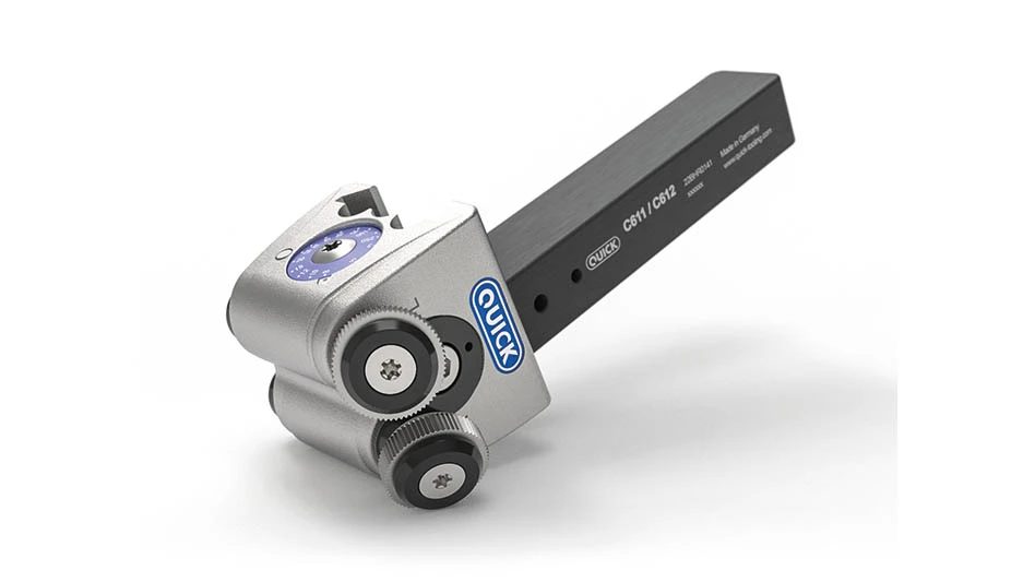
Thread mills are available in two main configurations: solid carbide tools and versions with inserted carbide blades. They typically fall into three categories – single-form, triple-form, and multi-form – each designed for specific threading applications.
Another key advantage of thread mills is versatility – one tool size can machine larger internal threads with the same pitch. In many cases, the same thread mill can produce right-hand and left-hand threads simply by modifying the CNC machine’s toolpath.
Most thread mills feature right-hand flutes and are designed for right-hand cutting. However, left-hand spiral tools provide the added benefit of lifting chips upward out of the hole, improving chip evacuation in blind-hole applications.
When climb milling is preferred, thread milling typically begins at the bottom of the hole. This approach can increase side pressure, potentially requiring a spring pass to ensure thread accuracy. Alternatively, if climb milling is still desired but the operation starts from the top of the hole, a left-hand spiral, left-hand cutting tool must be used.
Grinding a thread mill on a multi-axis CNC tool grinding machine involves four key operations: blank preparation, flute grinding, thread form grinding, and relief grinding.
Blank preparation involves grinding the outer diameter of the threading section – allowing for stock removal – as well as shaping the neck diameter behind the thread.
Unlike taps, which typically feature a neutral rake due to cutting being performed by the chamfered lead at the tip, thread mills have a positive rake – like an end mill.
Special care must be taken when designing the thread form on a helically fluted tool. A 1:1 replication of the thread profile on the grinding wheel is only accurate when the flute is straight. Once a helical flute is introduced, angular compensation on the grinding wheel becomes necessary to account for distortion. Many CNC tool design software packages include built-in compensation features, or separate programs can perform the calculations. In practice, the compensation is typically minimal – for example, with a 20° helix and a 60° V-thread, the angular distortion is only about 1° to 2°.
Ideally, two different grit threading wheels should be used: one for rough grinding and the other for finish grinding. It’s important to remember a thread mill is a precision threading tool, and any wheel wear during production grinding can compromise the accuracy of the thread profile.
Finally, relief grinding creates the necessary clearance behind the cutting edge, similar to what’s done on a conventional cutting tap or the cutting edge of an end mill.
MyGrinding Inc.
https://www.mygrinding.com

Explore the May 2025 Issue
Check out more from this issue and find your next story to read.
Latest from Aerospace Manufacturing and Design
- Dassault Aviation unveils the Falcon 10X
- Industrial round bumpers
- Defense Industry Trends webinar with Greenwich Capital Group
- Air Astana finalizes order for 25 Airbus A320neo family aircraft
- Syensqo showcases high-performance sustainable composites at JEC World 2026
- Multi-axis laser processing system
- Daher accelerates industrialization of thermoplastic composite upcycling
- Orizon Aerostructures deploys Flexxbotics platform