Editor's Note: This article originally appeared in the March 2026 print edition of Aerospace Manufacturing and Design under the headline “CNC grinding operations – Indexable inserts.”


The concept of the throw-away carbide insert emerged in the 1950s. Today, indexable inserts are widely used as cutting tools in turning, milling, and drilling operations. Their manufacture typically involves pressing and sintering, followed by grinding and coating. In this article, we’ll focus on the grinding processes required to produce finished inserts.
The process begins with an automated CNC double-disc grinder grinding the top and bottom faces of the insert blanks. Depending on their size, the blanks are loaded in batches of tens or hundreds into a specialized carrier feeding them between two opposing large super-abrasive wheels. These machines grind both sides simultaneously, ensuring excellent parallelism and flatness. Because inserts are produced in high volumes, an automatic feeding system – such as a vibratory bowl – is often integrated into this stage of the process.
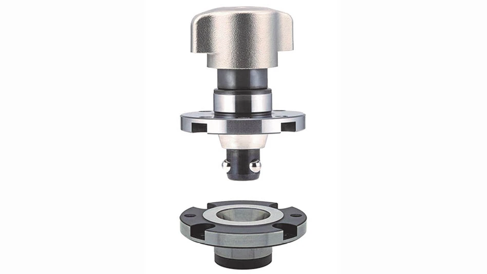
The center hole of an indexable insert is typically not ground after sintering; instead, it’s formed during the sintering process to a specific tolerance. In many designs, the thread in the toolholder is slightly offset relative to the hole in the insert. When the screw is tightened, the tapered underside of the screw head engages the tapered hole, generating a clamping force that pulls the insert downward and sideways against locating walls. To ensure precise positioning against the wall surface, the periphery must be ground to tight tolerances.
Periphery grinding is performed on dedicated, automated CNC grinding machines. The simplest inserts require only a single setup, in which both the peripheral contour and the radii of each indexable corner are ground in one clamping. Inserts with similar geometries but added features – such as a K-land (edge protection) – can often be finished in the same setup as well.
For more complex inserts, periphery grinders are used only for each of the indexable sides serving as locating surfaces. The actual cutting geometry is then produced on dedicated CNC insert grinders or multi-axis CNC tool grinding machines.
A common workholding method during grinding is the anvil-type holder applying clamping force from both sides of the insert. One side acts as the anvil, while the opposite side incorporates a pin locating the insert blank and pushing it firmly against the anvil. For inserts without a center hole, the holder uses two opposing anvils instead of a pin.
Another method, typically used on multi-axis tool grinders, is the nail-type holder where the clamping force is applied from one side by a pin (the nail) pulling the insert back against the workhead. This setup provides greater wheel access to the insert, enabling more complex grinding operations.
Grinding processes for more intricate inserts can include profiling (for lay-down and stand-up inserts), grinding rake angles, chip breakers, edge protection features, and more. Because indexable inserts are often considered throw-away tools, even highly complex geometries must be produced cost-effectively. As a result, single-clamping strategies and a high degree of automation are essential.
MyGrinding Inc.
https://www. mygrinding.com

Explore the March 2026 Issue
Check out more from this issue and find your next story to read.
Latest from Aerospace Manufacturing and Design
- The Lee Company opens Innovation Center
- Precision XY gantry system
- Archer to test Starlink onboard its Midnight air taxis
- System eliminates cage-creep in sliding bearings
- Bodo Möller Chemie signs worldwide supply contract with Airbus
- Sandvik Coromant's CoroTurn Plus turning adapter
- ZOLLER Technology Days & Smart Manufacturing Summit May 13-14, 2026 in Ann Arbor, Michigan
- Walter's TC620 Supreme multi-row thread mill family