 Electromagnetic interference (EMI) can cause avionic equipment performance to degrade or even malfunction. EMI can affect cockpit radios and radar signals, interfering with communication between pilot and control tower. Airborne devices that can cause interference include laptop computers, electronic games, cell phones, and electronic toys, and all have been suspected of causing events such as autopilot disconnects, erratic flight deck indications, and airplanes turning off course. EMI effects from lightning, solar flares, electrostatic discharge, and high-intensity radiated fields (HIRF) from radar and various kinds of transmitters or communications equipment – have all resulted in numerous aviation incidents throughout the years. As a result, EMI effects are now considered in all aspects of avionics design and certification.
New digital flight control systems need to be hardened to all of these EMI effects. Standards such as RTCA DO-160 for environmental conditions and test procedures for airborne equipment or the Defense Department’s MIL-STD-461 exist to control EMI issues. These standards limit unnecessary electronic emissions.
One major way to combat EMI is to provide shielding of various line replaceable units (LRUs) and harnesses. Shielding a device or system not only reduces EMI emissions, it improves susceptibility performance. With advances in wireless technology and increased device signal sensitivity, shielding becomes even more important to maintain the functionality and safety of avionic equipment.
What is an electromagnetic field?
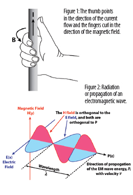
When electrical charges are present, either moving or stationary, they generate an electric field (E-field) between these charges. Oscillating or moving charges are called time-varying currents. If there is a current flowing, then there will be a magnetic field (H-field) generated. The direction of the magnetic field can be determined by the right-hand rule (Figure 1). Maxwell equations tell us that these moving charges (i.e., a current flow) will not only have a time-varying H-field, but will generate a time-varying E-field. This is then an electromagnetic field. The E-field and H-field components are mutually dependent and are transverse to each other (Figure 2).
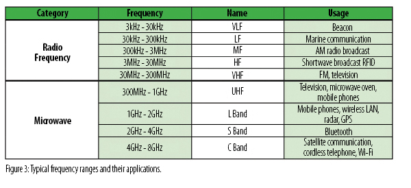
This electromagnetic field or potential EMI is unwanted energy that can disturb other nearby electronic devices, especially important with sensitive signal levels such as GPS and digital communications between systems. These electromagnetic fields are classified by frequency. Figure 3 illustrates some of these bands, and one can see how important it is to shield LRUs.
Control and planning
Avionic systems contain a large number of on-board, frequency-generating systems including frequency synthesizers, digital circuits, telemetry, and switching power supplies. Effective frequency management begins with a good tracking system or compilation list of all the frequencies and their significant harmonics, signal rates, rise/fall times, and power levels. Using this spectrum information during EMI analysis enables designers to avoid problems in establishing new frequencies and minimize incompatibilities among components based on their existing frequencies.
A good grounding plan, shield termination and interconnects, proper wiring classification and harnessing, and shielding are the main means of controlling system EMI. Many systems require shielding of enclosures, connectors, and harnesses starting at 60dB and ranging up to more than 100dB. Methods for achieving such levels include:
- Proper enclosure material
- Effective printed circuit board layout and design
- Ensuring resistance across enclosure continuities
- Effective gasketing between mating surfaces
- Properly terminating cable shields
- Proper conductive mating surfaces
What is shielding?
For effective shielding, the LRU should be completely surrounded by an electrically conductive material (Figure 4). Shielding effectiveness is dependent on the conductivity and thickness of the material and the frequency and amplitude of the electromagnetic field. However, shields have shortcomings such as weight, susceptibility to corrosion, wear, apertures and seams, and physical rigidity. Apertures and seams are especially critical as they allow leakage of electromagnetic energy and lower the shielding capability of the enclosure design. The bigger the size of the aperture or seam, the less shielding.
There are two basic approaches to reduce or shield electromagnetic emissions from a device or system and improve its susceptibility performance. One is shielding at the printed circuit board level using proper design. The second is to place the device or system in a shielded enclosure where gaskets can improve shielding of the enclosure. Shielding solutions are applicable for avionics packaging, enclosure shielding, radio packaging, canopy/window perimeters, structure gaps, and access cover plates.

Board level shielding
Available in a variety of sizes and heights, board level shielding (BLS) can be specified with any number of compartments. Board level shields are placed around the component or circuit(s) on the printed circuit board (PCB). They attenuate the amount of electromagnetic energy propagating from digital devices.
The effectiveness of BLS depends on the design of the PCB. Normally, the sixth side of this box will be a ground plane on the board. The number and spacing of vias and/or traces running from this shielded area to other board components can impact the effectiveness of BLS. With higher frequencies and shorter wavelengths, the size and number of holes can become issues. Capacitive and inductive coupling are more significant than aperture size for shielding.
Another issue with higher frequencies is resonance effect. These structures behave as cavity resonators. A 2" x 1/2" enclosure resonates at a first-order mode of around 12GHz. Even weak coupling at these extremely high frequencies can induce strong oscillations than can then couple to any other point in the enclosure.
Devices generate more heat as their frequency increases, so thermal management is also a design factor. Thermal management can be achieved through the use of thermal pads and heat sink.
Gasketing
Gaskets maintain shielding by properly treating seams. The effect of these seams and discontinuities, in general, accounts for most of the enclosure leakages. The shielding effectiveness of a seam is dependent on the materials, contact pressure, and surface area. If there is no continuity between metal pieces, then it will become a radiating aperture. Although close-spaced fasteners (approximately 25mm) can be used alone, gasketing is preferred to reduce the number of fasteners and compensate for mechanical variations or joint unevenness.
 Beryllium copper (BeCu) gaskets offer the highest level of attenuation across the widest frequency range and are useable in both compression and shear-type applications. Solid fingers have a greater cross-sectional area, hence higher conductivity, and the finger shape has the characteristics of an interconnecting ground plane with a large contact area. The inductance will be low, and the movement of the finger shape will provide a wiping action that aids in penetrating or removing any oxide buildup in the contact area. Finger-stock gaskets are very forgiving to compression, meaning it is very difficult to over-compress them and cause compression set or breakage. Potential problem areas are the slots between the fingers. At sufficiently high frequencies, these slots begin to permit radio frequency (RF) energy transmission through the bounded slot configuration.
Factors to consider during gasket selection are RF impedance, shielding effectiveness, material compatibility, corrosion control, gasket height, compression force, compressibility, compression range, compression set, and environment. For RF impedance control, high conductivity and low inductance is desired. BeCu has the highest conductivity.
Orbel Corp.
www.orbel.com
About the author: Ed Nakauchi is a technical consultant for Orbel Corp. and can be reached at 610.829.5000.
Explore the April May 2015 Issue
Check out more from this issue and find your next story to read.
Latest from Aerospace Manufacturing and Design
- Upcoming webinar to highlight the rise of electric vehicles
- JEKTA, ZeroAvia partner on hydrogen-electric amphibious aircraft
- Mastercam 2025 software
- IMTS 2024 Conference: Cutting Edge Innovations: Maximizing Productivity and Best Practices with Superabrasives
- Eve Air Mobility unveils first full-scale eVTOL prototype
- Dillon Manufacturing's Fast-Trac Jaw Nuts
- IMTS 2024 Conference: Breaking the Tradeoff: Utilizing Deep Learning AI with X-ray Computed Tomography for Unparalleled Clarity and Speed
- #47 - Manufacturing Matters - The Ins and Outs of CMMC 2.0 with Smithers Information Security Services


